MLZ is a cooperation between:
 > Technische Universität München
 > Helmholtz-Zentrum Hereon
 > Forschungszentrum Jülich
MLZ is a member of:
 > LENS
 > ERF-AISBL
MLZ on social media:

MLZ (eng)
Lichtenbergstr.1
85748 Garching
KWS-2
Small angle scattering diffractometer

This instrument is focussed on cold neutrons. Therefore, please carefully check the “Technical data WITHOUT cold source” section. Deviating parameters are in bold. The instrument team is happy to answer any further questions!
KWS-2 [1] is a classic small-angle scattering diffractometer at which a large Q range between 2.0 × 10⁻⁴ and 2.0 Å-1 can be explored with high neutron intensity and a tunable resolution [2, 3]. The broad Q range is currently covered by combining in a versatile, user-friendly approach the SANS (conventional pinhole), USANS (focussing lenses) and WSANS modes with corresponding detectors [4-6]. In the conventional pinhole mode, the wavelength λ and the sample to main detector distance LD can be varied between 2.8 and 20 Å and from 1.25 to 20 m, respectively, to maximise the Q-range. The main SANS detection system of KWS-2 consists of an array of 3He tubes (Ø = 8 mm) and rapid read-out electronics [3].
In focussing mode, parabolic MgF2 lenses are used in combination with a small aperture at the entrance of the collimation system and a secondary scintillation-type high-resolution detector (HRD) that can automatically be brought in beam on demand [1, 4]. The WANS detector, which is also an array of 3He tubes (Ø = 6 mm), is placed in an inclined position below the beam axis at a distance LD = 1.25 m downstream of the sample. It provides the possibility to record scattered neutrons in a wide angular range (up to 50° scattering angle [5, 6]) and to discard the inelastic component from the measured data by TOF analysis to improve the signal-to-noise ratio on demand [7].
The KWS-2 provides a very high neutron flux on the sample. This is the result of the combination of a neutron guide system that was specially designed to transport high intensity to the instrument [8, 9] and a versatile velocity selector (Airbus, Germany). It enables an easy selection of the wavelength λ and wavelength spread Δλ/λ, depending on whether the specific scientific experiment demands an improved resolution, thus
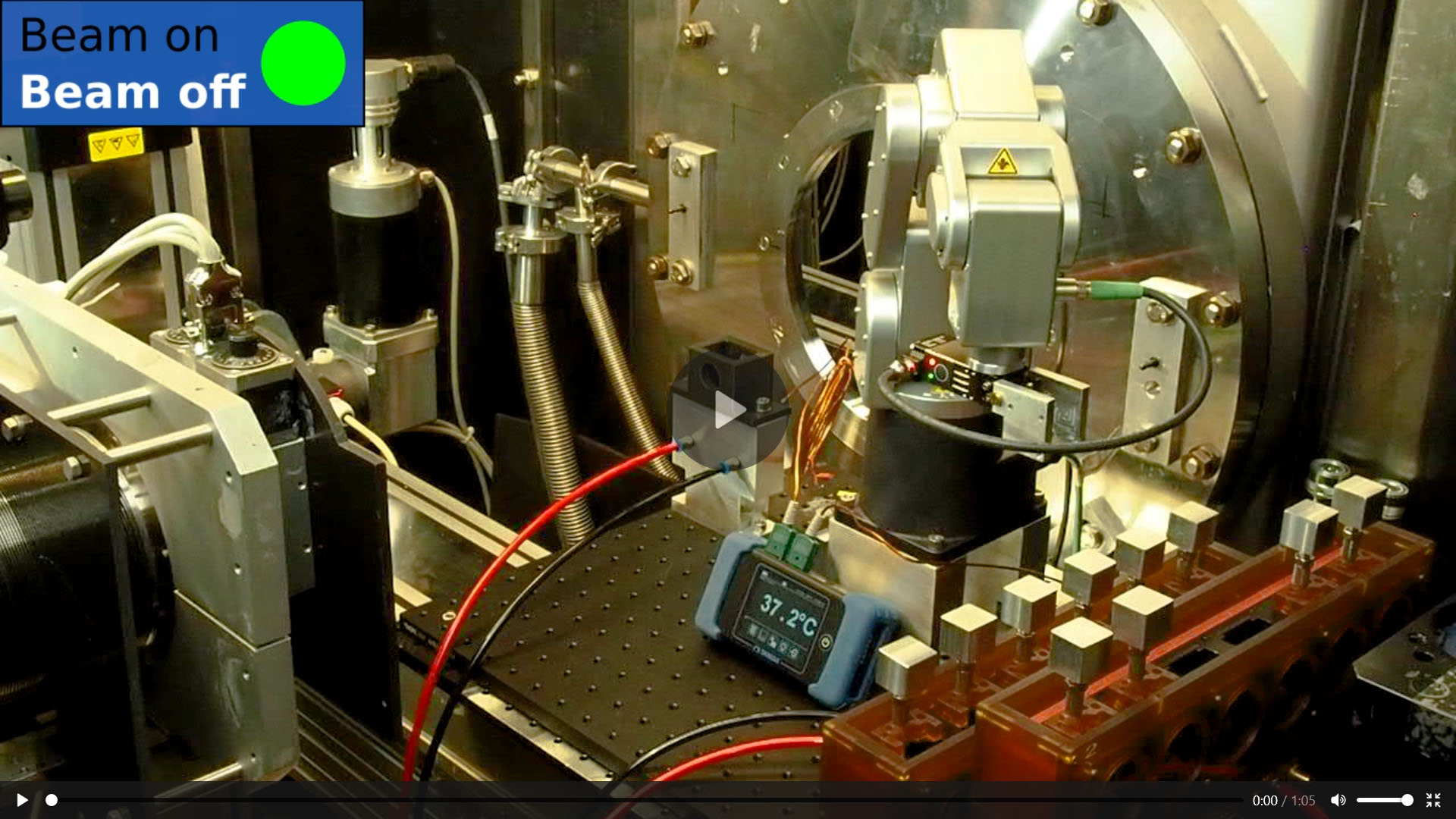
The high-flux option enables scientific opportunities in the structural investigation of small soft-matter and biological systems aiming at time-resolved SANS (TR-SANS) investigations due to fast kinetical processes with a time resolution of a few tens of ms. It also provides the conditions for optimal utilisation of beam time by acquiring data in a shorter time than other SANS diffractometers. The installation of robotic elements and an automated sample changer at the sample position allows a continuous supply of samples to the instrument and the merging of experiments from different user teams when similar experimental conditions are required, contributing even more to the efficient use of the beam time.
Finally, using the mechanical monochromator in an inclined position to the beam axis offers the availability of thermal neutrons (λ = 2.8 Å) at the instrument.
[1] A. Radulescu et al., J. Phys. Conf. Series 351, 012026 (2012).
[2] A. Radulescu et al., J. Appl. Cryst. 48, 1860 (2015).
[3] J. Houston et al., J. Appl. Cryst. 51, 323 (2018).
[4] A. Radulescu et al., J. Vis. Exp. 118, e54639 (2016), KWS-2 video.
[5] A. Radulescu et al., EPJ Web Conf. 286, 03006 (2023).
[6] A. Radulescu, J. Appl. Cryst. 57, 1040 (2024).
[7] L. Balacescu et al., J. Appl. Cryst. 54, 1217 (2021).
[8] A. Radulescu, Ioffe, A., NIM-A 586, 55 (2008).
[9] A. Radulescu et al., NIM-A 689, 1 (2012).
- Colloids, nanocomposites, gels
- Polymer blends, diblock copolymers
- Microemulsions, complex fluids, micelles
- Membranes, films; in-situ adsorption – desorption/ humidifying – drying phenomena
- Shear-induced micelle deformation, rubber network deformation, nanocomposite ordering
- Proteins structure; folding/ unfolding
- Protein-polymer complexes for delivery of different active agents (drugs, nutrients, etc.)
- Nanoparticles for drug delivery
- Semi-crystalline polymer films and solutions
- In-operando ion exchange membranes: in-beam controlled humidity and temperature with conductivity measurements
- Anton-Paar fluid rheometer, steady and oscillatory shearing
- Stopped flow device
- Automatic sample changer: 48 positions carousel with temperature control
(5 to 85 °C) , up to six different temperatures on groups of cuvettes (Hellma, banjo-type) - Robot arm for continuous supply of the carousel with sample cuvettes
- 8 positions and 2 × 6 positions thermostated (Peltier) sample holder (-40 … 150°C) with controlled atmosphere chamber
- Humidity chamber (8 positions) with temperature control (10 to 85 °C) and high-precision humidity generator (10 to 90 % RH) with H2O and D2O reservoirs for quick in-situ contrast variation
- Stretching apparatus (four devices in a common set-up) for controlled stretching in-beam
- FT-IR spectroscopy, transmission and ATR geometry
- MALS
- In-beam SEC
- Q = 0.003… 2 Å-1 (see gallery, fig. 2)
- Flux (with ’10 %’ selector)
- 0.4 × 10⁷ n cm-2 s-1 for λ= 2.8 Å
- 1 × 10⁷ n cm-2 s-1 for λ= 5.0 Å (see gallery, fig. 5, 6)
- Astrium, Δλ/λ = 14 – 20 % (tilted selector), λ = 2.8… 7 Å (see gallery, fig. 4-6)
- Δλ/λ = 10 % on request (lower flux)
- Tunable Δλ/λ: 20 %… 2 % (TOF analysis) (see gallery, fig. 3)
- 2 m, 4 m, 8 m, 14 m, 20 m, sample position
- Rectangular 1 × 1 – 50 × 50 mm2
- XYZθ translational-rotational stage + cradle
- Accuracy better than 0.01°, 0.01 mm
- Robot arm with multiple positions cuvette carousel
- 1-disc with 8 opening windows: 1 × 1 cm2, frequency 10 – 45 Hz
- TOF data acquisition in the high-Q regime (1 – 4 m detection distance)
- Separation of the inelastic and elastic scattering from the hydrocarbon systems
- Detection range: continuous 1 – 20 m
- 3He tubes array, active area ~0.9 m2
- Count rate for no deadtime > 2 MHz
- Resolution ≤ 8 mm
- Efficiency 88 % for 5 Å, 75 % for 2.8 Å
- Semi-transparent beamstop, simultaneous measurement of transmission and scattering
- TOF and list-mode available
- 3He-tubes, active area 0.68 × 0.5 m2
- Detection range: fixed position, 1.25 m after the sample, inclined against the beam axis for a detection up to 50° scattering angle
- Position resolution ≤ 5 mm
- Efficiency 88 % for 5 Å, 75 % for 2.8 Å
- TOF and listmode available
- Q = 0.0002… 2 Å-1 (see gallery, fig. 2)
- Flux
- 1 × 10⁸ n cm-2 s-1 for λ= 4.5 Å for standard resolution (see gallery, fig. 5, 6)
- 2 × 10⁸ n cm-2 s-1 for λ= 4.5 Å for relaxed resolution
- Astrium, Δλ/λ = 10 – 32 % (tilted or straight selector), λ = 2.8… 20 Å (see gallery, fig. 4-6)
- Tunable Δλ/λ: 10 %… 2 % (TOF analysis)
- 2 m, 4 m, 8 m, 14 m, 20 m, sample position
- Rectangular 1 × 1 – 50 × 50 mm2
- XYZθ translational-rotational stage + cradle
- Accuracy better than 0.01°, 0.01 mm
- Robot arm with multiple positions cuvette carousel
- 1-disc with 8 opening windows: 1 × 1 cm2, frequency 10 – 45 Hz
- TOF data acquisition in the high-Q regime (1 – 4 m detection distance)
- Separation of the inelastic and elastic scattering from the hydrocarbon systems
- MgF2 cooled parabolic lenses (70 K), grouped in 3 packages for focussing of different wavelengths (7 Å, 10 Å, 18 Å)
- Detection range: continuous 1 – 20 m
- 3He tubes array, active area ~0.9 m2
- Count rate for no deadtime > 2 MHz
- Position resolution ≤ 8 mm
- Efficiency 88 % for 5 Å, 75 % for 2.8 Å
- Semi-transparent beamstop, simultaneous measurement of transmission and scattering
- TOF and list-mode available
- 3He-tubes, active area 0.68 × 0.5 m2
- Detection range: fixed position, 1.25 m after the sample, inclined against the beam axis for detection up to 50° scattering angle
- Position resolution ≤ 5 mm
- Efficiency 88 % for 5 Å, 75 % for 2.8 Å
- TOF and list-mode available
- Scintillation: round, 9 cm active area
- Detection range: fixed position at 17 m after the sample
- Used together with lenses and a small entrance aperture (4 × 4 mm2) at 20 m collimation length
- Variable sample aperture between 10 × 10 mm2 (quadratic) and Ø = 5 cm (round)
Instrument scientists
Dr. Aurel Radulescu
Phone: +49 (0)89 158860-712
E-mail: a.radulescu@fz-juelich.de
Dr. Anastasiia Fanova
Phone: +49 (0)89 158860-606
E-mail: a.fanova@fz-juelich.de
KWS-2
Phone: +49 (0)89 158860-510
Operated by

Funding

Video: Roboter changes samples
Publications
Find the latest publications regarding KWS-2 in our publication database iMPULSE:
Citation templates for users
In all publications based on experiments on this instrument, you must provide some acknowledgements. To make your work easier, we have prepared all the necessary templates for you on this page.
Instrument control
Gallery


MLZ is a cooperation between:
 > Technische Universität München
 > Helmholtz-Zentrum Hereon
 > Forschungszentrum Jülich
MLZ is a member of:
 > LENS
 > ERF-AISBL
MLZ on social media:


